OtO Power Connector Re-Design
During my 5th co-op at OtO Lawn, my main project was to re-design a connector that customers use to charge the OtO smart sprinkler device. This connector was causing many failures and returned units in the field. It became one of the highest causes of returned units and needed to be improved.
The Problem
I identified two problems with the current connector after analyzing many of the returned units.
- Fragility. The connector housing is held together by a thin plastic collar and it is far too weak. It can easily break from the tension force caused by detaching the two ends of the connector. The diameter of the metal charging pins is also too small, allowing them to be easily bent or snapped when mishandled.
- Corrosion. Since this connector is intended for outdoor use near a sprinkler system it will inevitably get wet. This connector does not seal effectively and due to the current flowing through the connector, it corrodes.
Corrosion combined with fragility results in the pins snapping off and the OtO can no longer charge. At this point the entire device must be returned and replaced.
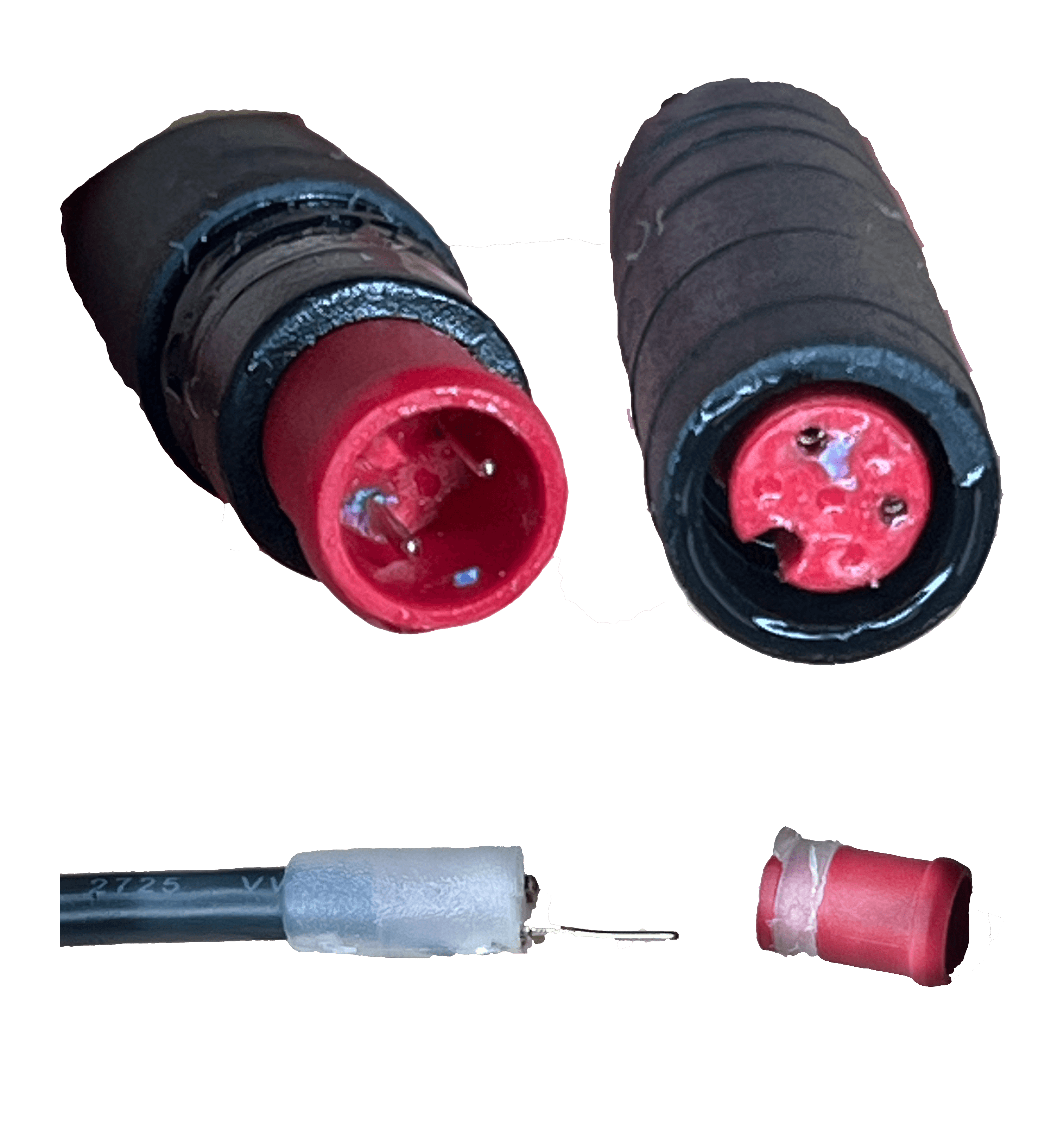
Top: Corrosion and water observed inside connector
Bottom: Broken plastic tab that is supposed to hold connector together
Testing
After discovering the problem, I researched more robust connectors with better seal designs and thicker electrical contacts. I ordered many samples of various designs and would use testing to validate a new connector. To solve the fragility problem, cycle, force, and durability testing was done by hand. These tests quickly narrowed the field to ones that were far more robust. The more complex aspect of testing was looking at ingress protection. A submersion test was developed that places a connector underwater and passes 0.2-0.6A at 12V. This is done over an extended period of time allowing for any corrosion to form. A power supply and resistors were used to dissipate the power as heat. The connectors were periodically opened to look for ingress but also the current was monitored as a failure indicator. If a connector corrodes, the contact resistance increases and at a fixed voltage, the current should drop. Through the current data, connectors could be compared head-to-head as to which are best at resisting corrosion in a rugged environment.
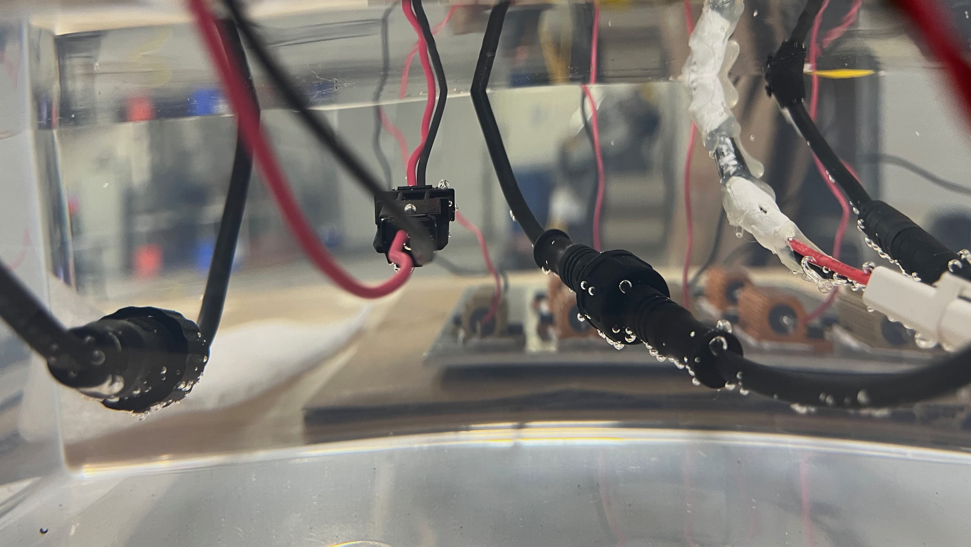
Water Submerged Connectors
Connector Selection
There were two connector designs that passed the robustness tests and also showed no signs of ingress or current drop after a few weeks. The next step was to evaluate the two from a user experience standpoint. One connector seemed much more user-friendly than the other and was ultimately the option that got pursued. This connector is a standard 2.1mmx5.5mm barrel jack that is commonly found on laptop chargers. The design can be bent, twisted, pulled, etc... without being damaged. On top of that, it can be inserted in any orientation. To seal, this connector has an o-ring that acts as a face seal when compressed using an external thread.
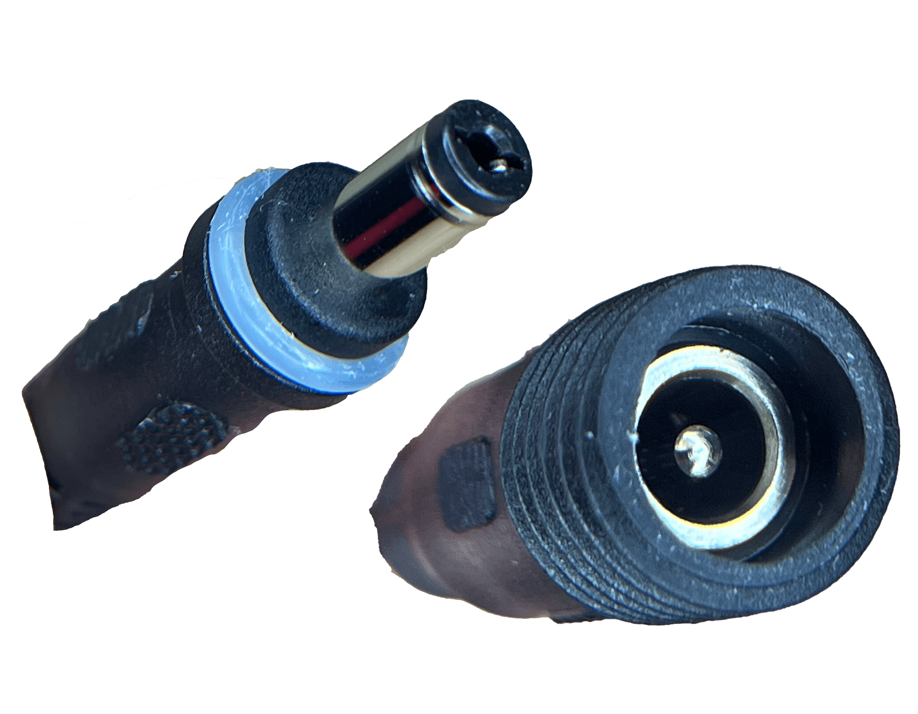
Connector Design that Performed Best in Testing and Further Pursued for Implementation
Design Limitations
When you implement a particular design releasing it to thousands of consumers, it is important to know the conditions in which it performs best, and when it can fail. At this point, I knew the connector would seal when submerged a few centimeters at room temperature. I also wanted to know if the sealing capabilities would be affected by temperature as this product operates in both hot and cold conditions. So I built a similar submersion test but this one cycles hot and cold water every 30 minutes into the chamber. I built this fixture using solenoid valves connected to hot and cold water lines, a Raspberry Pi, a relay, and a Python script. We found that under extreme temperature fluctuations, the O-ring fails to seal. The best explanation for this is compression set where the O-ring loses it's elasticity due to the large temperature differences. However, this test is far more rigorous than what the connector would see in the field, but it is still valuable to know the limitations of your product.
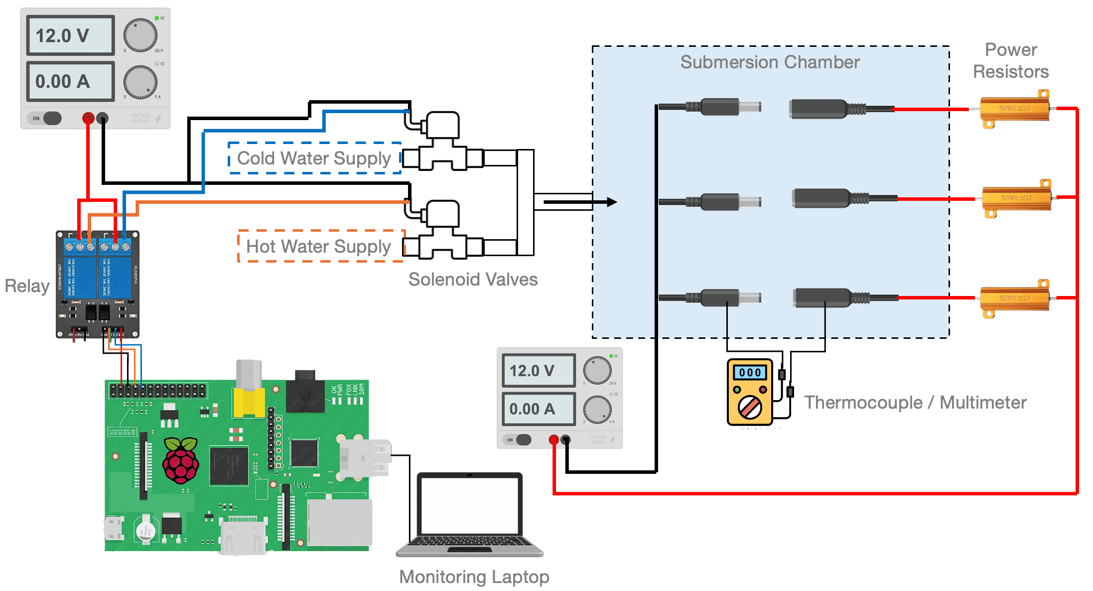
Schematic of Hot-Cold cycling Test Fixture
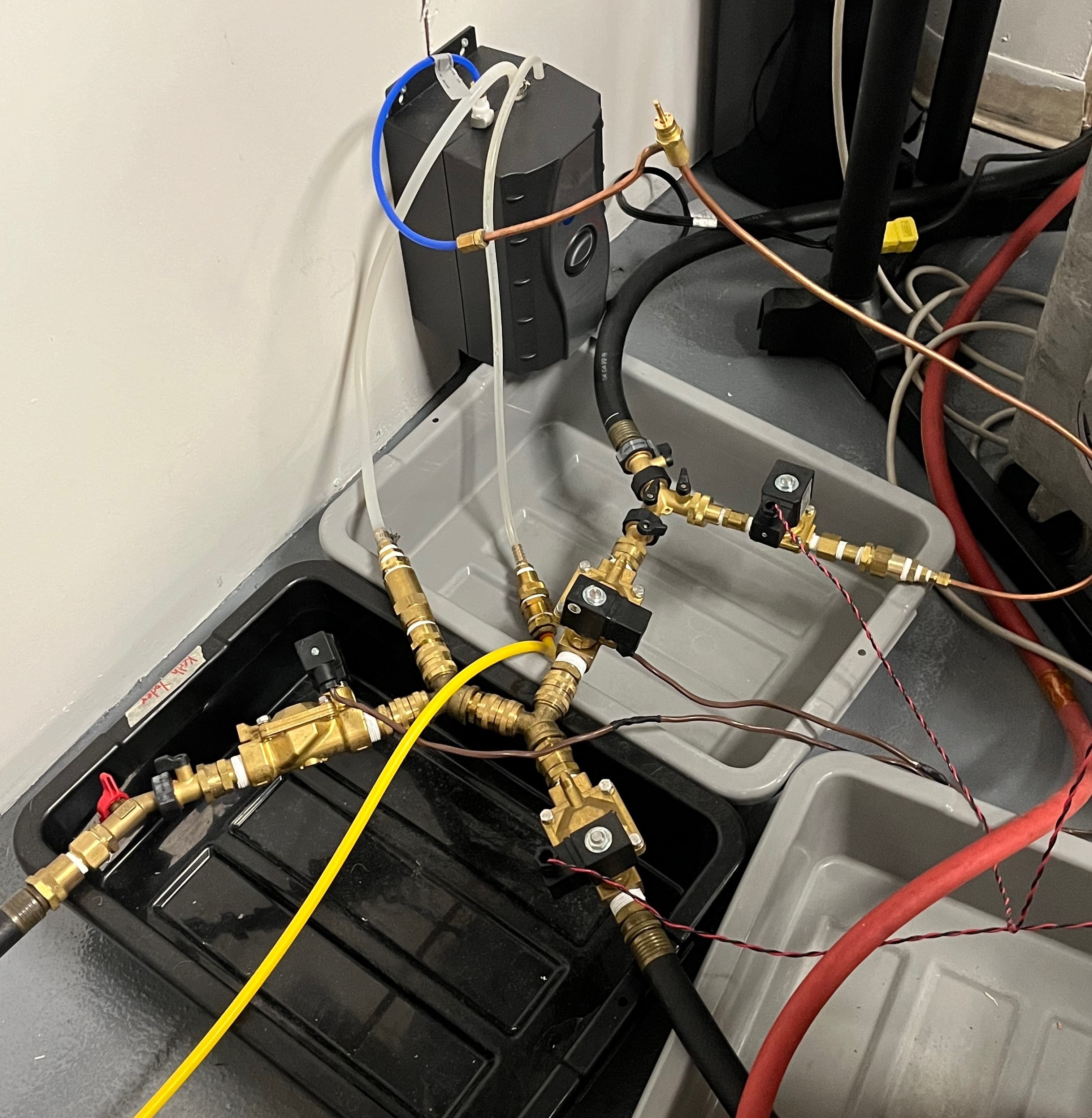
Piping and Valving of Test Fixture
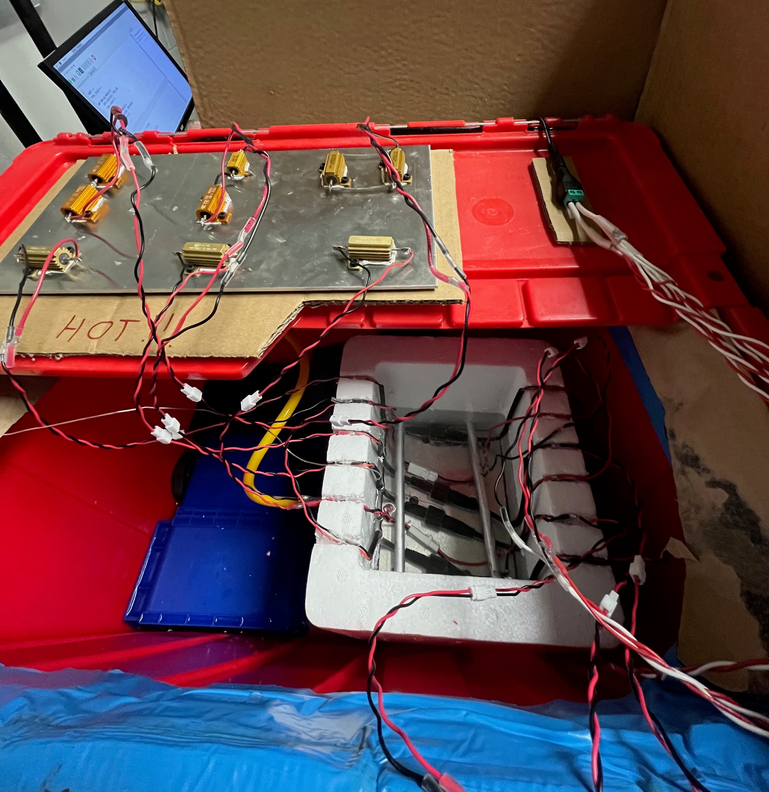
Test Fixture with Insulated Chamber, Wiring, and Power Resistors
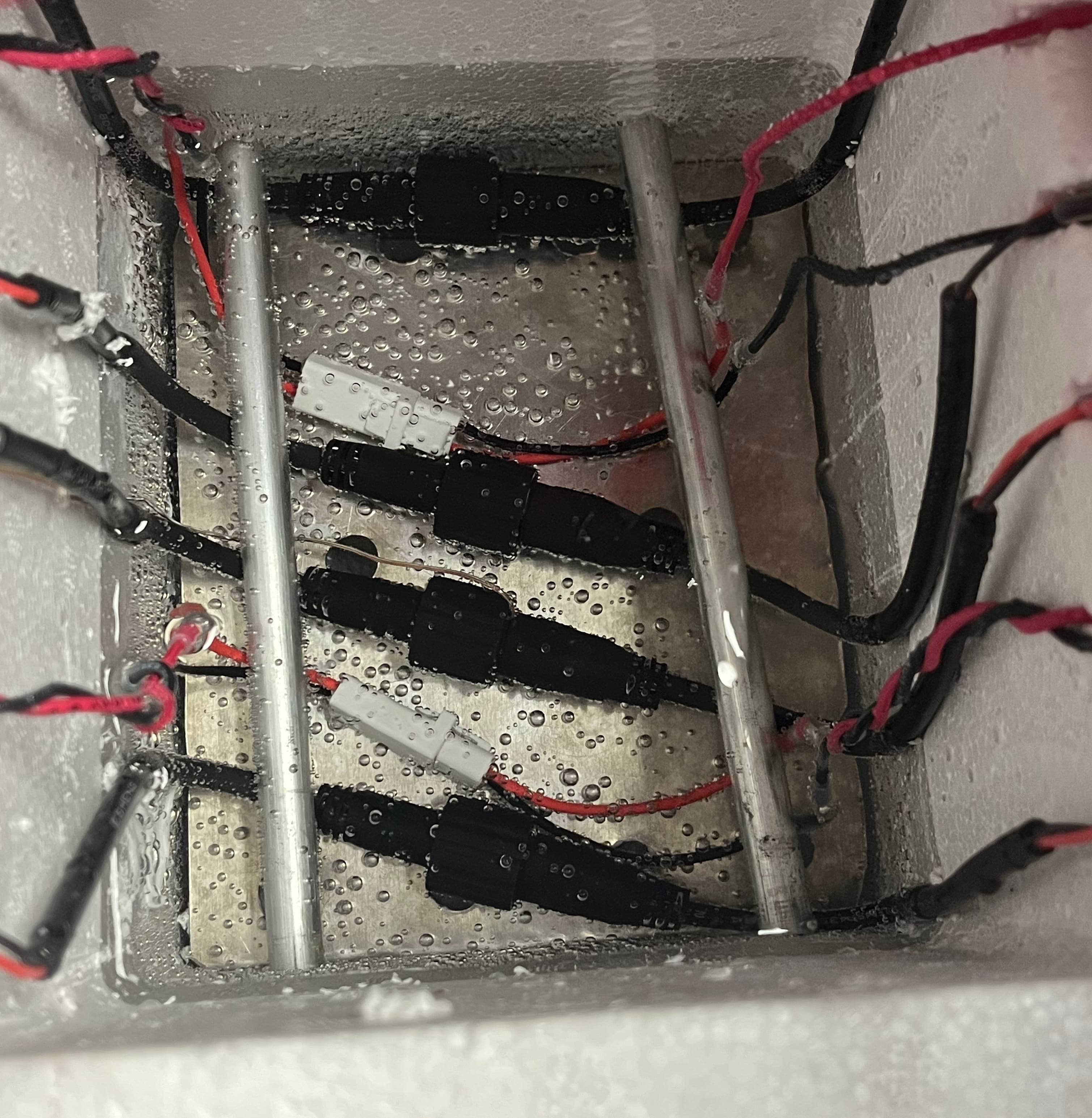
Connectors Submerged in Hot Water Chamber
Product Attachment
The selected connector next had to be attached to the product in a way that was easy to assemble using the current production processes. Changing the connector itself was easy and just a matter of soldering a new component to the charging cable. The interesting design came from what happens when the connector is not being used, for example when the device is running on solar power. The barrel side of the connector is found on the charger that is provided to the user. The jack side of the connector needs to seal so that it doesn't get wet when not connected. The jack also needs to securely attach to the product. To resolve these problems, I used SolidWorks to design a rubber plug (seen in orange) that fills the jack side of the connector and is easily removed by the user. I also worked on a snapping mechanism that holds the connector to the base plate found on the bottom of the device. I iterated using 3D printing and eventually finalized a design.
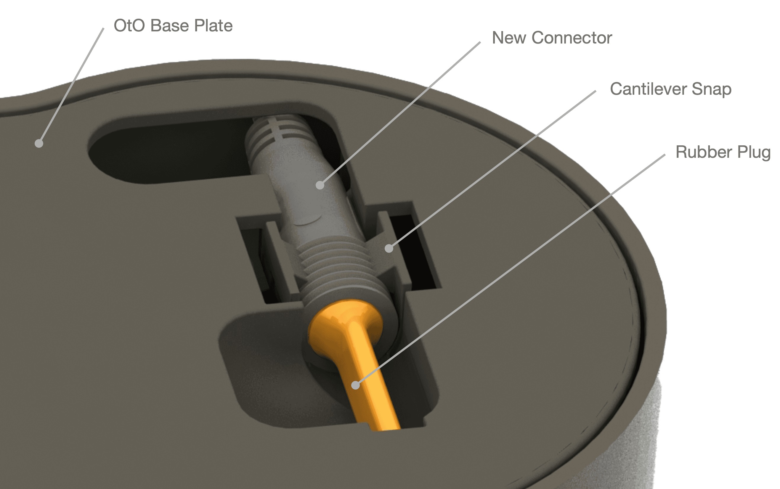
CAD of Proposed Design
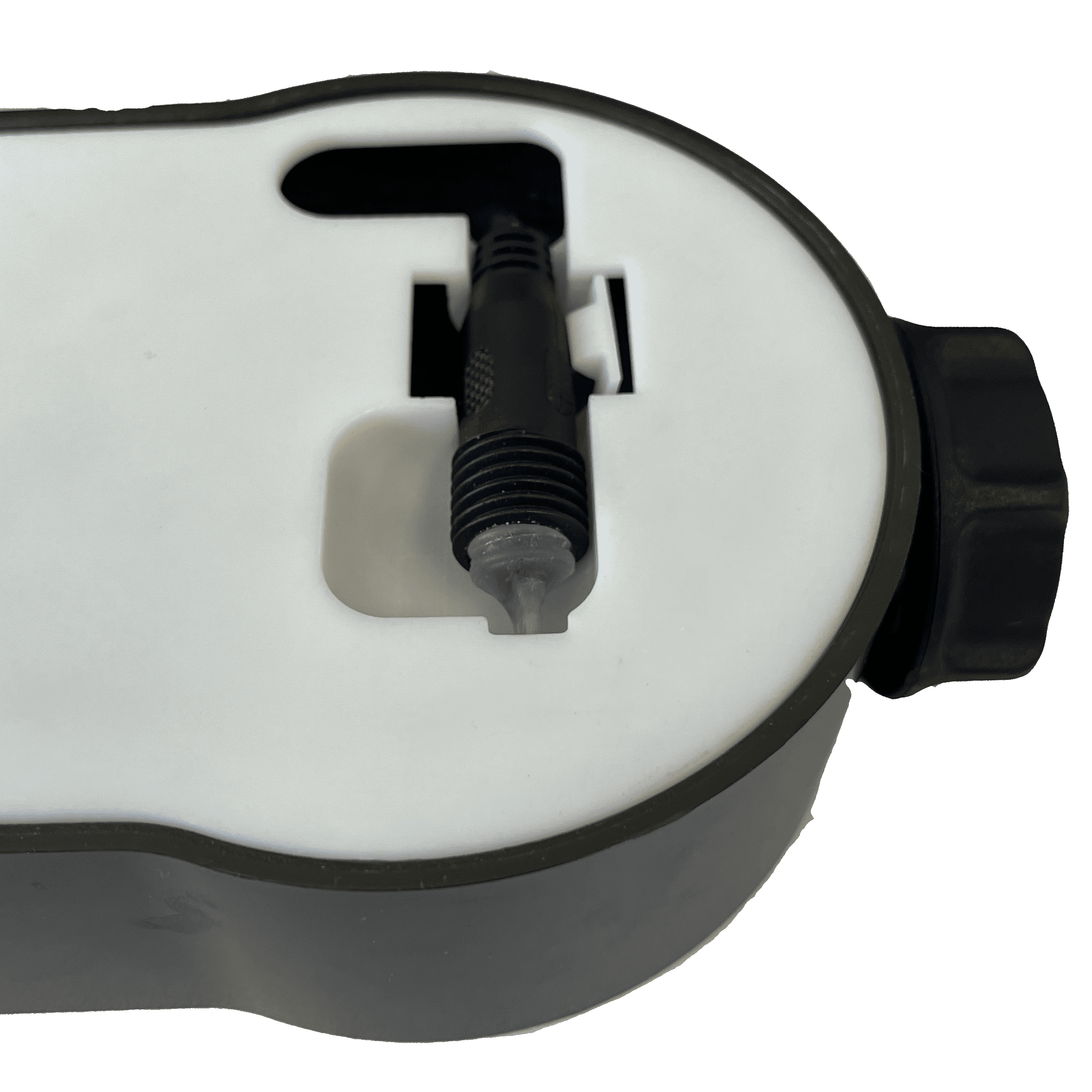
Physical Prototype of Snapping Mechanism and Plug
Analysis
I also conducted FEA studies to ensure the injection moulded snap on the base plate would not yield. The required deflection was calculated to create a crisp snapping mechanism and this was also simulated using FEA. FEA was a great way to validate the design before sending it out for production. My study included applying the known deflection required for the connector to snap in, and ensuring the stress levels were still in the elastic region.
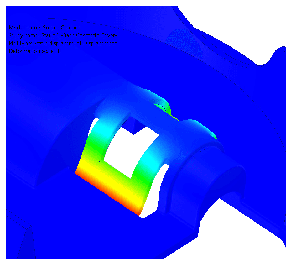
Deflection Study
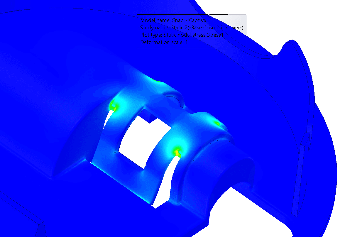
Stress Study
Takeaways
This was a great project where I got to take an end-user problem and solve it using testing as my source of truth. Building a test fixture from scratch, and using data to prove that a design works is a great exercise for an engineer that provides a lot of confidence when supporting design choices. I also got to partake in high-responsibility DFM work since the snapping mechanism will be injection moulded on 80,000 units next year. I wish I got to work more with OtO's part manufacturer to develop the tooling to produce my part, but unfortunately my co-op had ended by this point.